the case of the haunted level shifter
One of my favorite things about taking on non-hourly work is that I can relax a little bit more while I’m working without feeling bad about it. I had a new board come in to bring up over the holiday break, and so I decided it would be a nice diversion from my normal holiday routine (that is to say, using a bicycle to heap abuse onto my body) to crack a Pacifico and do some good old EE-lab work.
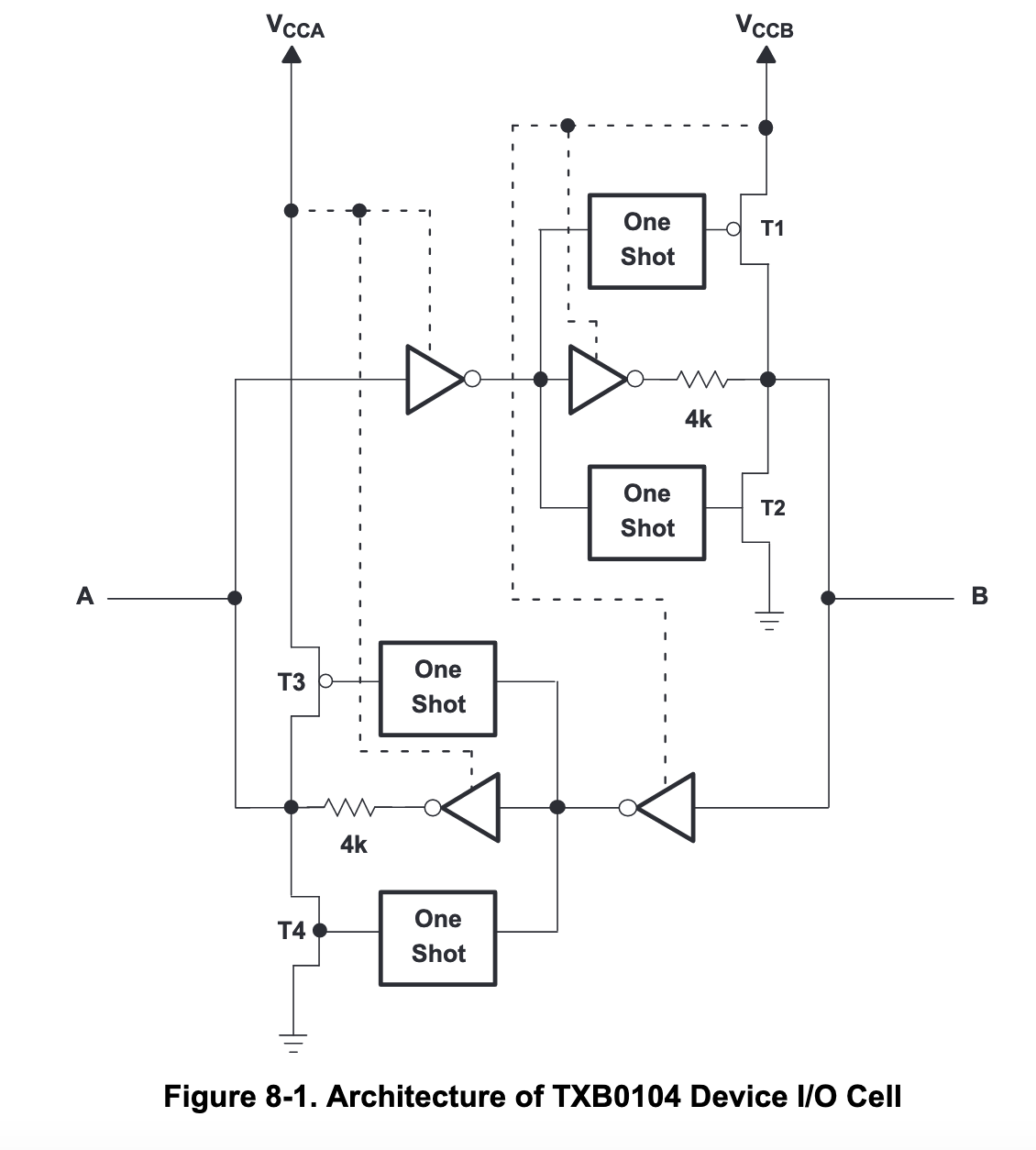
Much of the board bringup was going well — I had a STM32 eval kit, an FPGA eval kit, and a third custom board with some level shifters and some glue logic on it. The general setup was that all of the components were connected together by .1”-pin-header fly wires, and it was time to begin checking out the level shifter board. This board used a TI TXB0104 auto-direction-sensing level shifter to do the work of translating from the 3.3V STM32 I/O rails down to the 1.8V I/O rails that the rest of the system would use; I find these devices to be particularly creepy in how they sense which way to translate, and I’d run into some trouble with them before (especially if there are pull-up or pull-down resistors elsewhere in the system). All the same, I’d reviewed the schematic before the board went out to fab, and I didn’t see any of the obvious ways for one of these things to go wrong… so, in theory, it should work just fine, right?
I wrote a few lines of code to run on the STM32 to drive a constant level on the output, a signal I called “RESET_3V3”. On power on, it would drive it low for a second, and then it would drive it to a constant high level from then on. I got to work probing: I touched my multimeter probe to the 1.8V version of the signal, “RESET_1V8”, and was dismayed to find: it was being held at a constant 1.0V. I asked the STM32 to cycle the signal, and found that it sometimes went to 0, and sometimes didn’t, and sometimes went all the way to 1.8V, and sometimes didn’t. If I disconnected and connected the “RESET_3V3” flywire, the behavior changed. I had a few other level-shifted signals; I tried this on “TRIG_3V3” (and its shifted pair, “TRIG_1V8”), and found that the behavior was quite similar indeed. At one point, I probed out “RESET_3V3”, and found that it didn’t seem to be going all the way to 3.3V either, but later it did seem to drive all the way to the rail.
I looked in suspicion at the empty bottle, and went to bed.
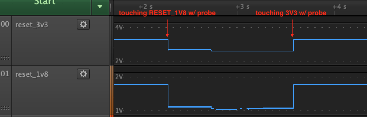
I came back to it this evening, and decided to take a more methodical approach. I hooked up my Saleae mixed-signal analyzer to the RESET_3V3 and RESET_1V8 test points, and was disturbed to discover that there was, apparently, no issue at all: the RESET_3V3 pin swung happily from 0V to 3.3V, and the RESET_1V8 pin swung happily from 0V to 1.8V. What gives? I pulled out my multimeter, and touched the RESET_1V8 test point, and… instantly, both nets collapsed, and stayed there: RESET_1V8 down to 1.0V, and RESET_3V3 down to 2.6V.
This was very disturbing. The TXB0104 has a 4K resistor in series with its output driver. It should not be capable of causing a meaningful drive fight with the STM32. The STM32’s GPIO drivers can source tens of milliamps of current. No matter what is happening on the output, there should be no way that RESET_3V3 should be drooping.
I continued probing around, suspicious that the voltage rails or grounds may have been inadequate in some way. In so doing, I found something even more disturbing: upon touching my multimeter’s probe to the test point for the 3.3V rail, the collapsed RESET nets both instantly recovered to their correct voltages. This was, for the most part, repeatable: touch RESET_1V8 (and measure it at 1.0V); touch RESET_3V3 (and measure it at 2.6V); touch VDD_3V3 (and measure it at 3.3V); touch RESET_3V3 (and measure it at 3.3V); rinse, and repeat.
How could this be? Perhaps I had a bad fly wire, with a high impedance? I put the system into the failing state by touching RESET_1V8 with the meter probe, then touched the RESET_3V3 test point (yep, still measured 2.6V), then finally touched the RESET_3V3 pin, this time on the other end of the fly wire. Aha! Got it! It measured 3.3V! And… now it measured 3.3V on the test point. This was extremely disturbing. Apparently touching the STM32 side of the reset wire caused the system to recover.
I have been hosed by TXB010x in many ways before, but this one seemed new, and worse, I couldn’t even blame it on the level shifter yet. I was running out of ideas, but cranked the Saleae up to 50Msps, in the hopes that there were oscillations that I just was not seeing at the lower frequencies I was measuring at. I saw… nothing.
I looked one more time at the datasheet for the TXB0104. (Good reading, by the way.) They gave the usual crapola that you see in every datasheet: “PCB signal trace-lengths must be kept short enough so that the round-trip delay of any reflection is less than the one-shot duration, approximately 10 ns, ensuring that any reflection encounters low impedance at the source driver.” Yeah, yeah, we get it, always use good decoupling and always use good routing, but these were DC signals — how bad could it be?
I did the math quickly. 10ns was 50MHz. I would not be seeing squat at 50Msps.
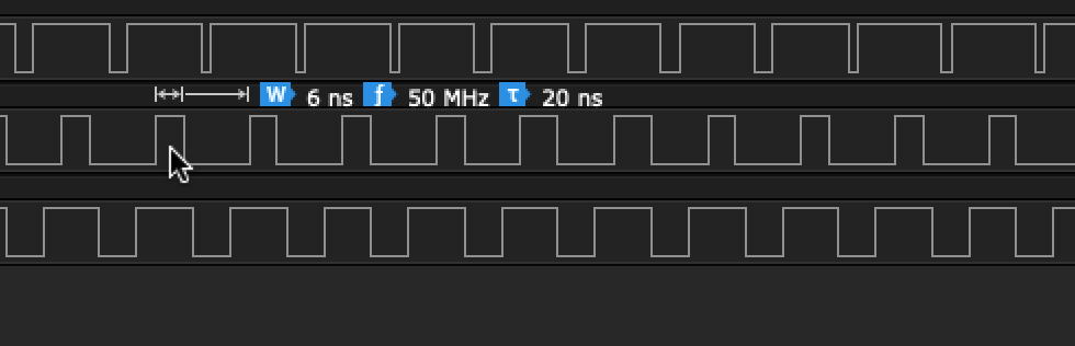
I put the Saleae into digital mode, and cranked it up to 500Msps. Here’s what I saw:
If you described the symptoms to me, I would tell you that you, too, should consider not mixing engineering and la mejor cerveza del mundo. I would not believe it, except that I had seen it with my own two eyes.
But the only explanation that fell out made plenty of sense. Best I could tell, what was happening was this: when I touched the meter probe to the floating RESET_1V8 test point, the capacitance from the meter probe was disturbing the TXB0104, and convincing it that the RESET_1V8 side was trying to drive a zero onto the RESET_3V3 side. In order to speed up transitions, the TXB0104 has “one-shot” drivers that fire for 10ns or so (without the 4k resistors) around edges. So the TXB0104 went and pumped a zero down the wire to RESET_3V3. Much like Punxsutawney Phil, it then saw its shadow — or, well, the reflection, anyway, of the signal, heading down the 6”-long fly wire. The reflection caused it to fire the one-shot drivers on both sides (RESET_3V3 and RESET_1V8), which kicked off another reflection on the long RESET_3V3 wire, and away it went, oscillating endlessly. The half-way voltages were not half-way voltages at all: they were just very high speed signals that I could not measure
It makes sense that touching the probe to the far end of the RESET_3V3 line added enough capacitance, as well, to dampen the reflections. The only unexplained thing is why touching the 3.3V rail dampened it. I still have no idea why that happened.
This is, by far, one of the wackiest and most distressing things I’ve seen so far. I guess the lesson learned is that TI’s TXB auto-sensing level shifters are cursed in more ways than just the pull-up problem. They seem convenient. They’re not. Don’t use them. They will bite you.
It is amazing how much there is to keep learning. The fact that this happened on a low-speed (in theory, DC!) circuit with standard components that everyone designs in was truly a surprise. I wonder what I’ll stumble upon next.